Solar guide · Shadow calculation table
Estimating Shadow Direction from Solar Angles
Calculate a Perth shadow bearing and length step by step from solar azimuth, altitude, and a two-metre object height.
- Published
- Updated
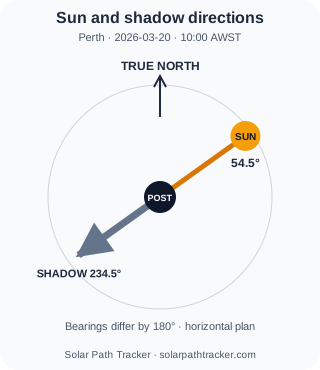
Which way would a two-metre garden post cast its shadow at 10:00 in Perth? Load the calculated example below to get the Sun’s bearing and altitude, reverse the bearing, then calculate a level-ground shadow length. Before applying it to a garden, check that the post is vertical and direct sunlight actually reaches it.
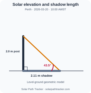
Length needs another assumption. For a vertical object on level ground, the shadow-length-to-height ratio is 1 ÷ tan(solar altitude). This idealized relationship is useful for scale intuition, but a real result changes with sloped ground, tilted objects, irregular shapes, diffuse light, and intervening obstructions.
Reverse the bearing, then check altitude
To reverse a solar bearing, add 180°. If the result is 360° or more, subtract 360°. The direction is meaningful for direct sunlight only when the Sun is above the horizon and reaches the object without being blocked.
Altitude controls the theoretical length. At 45°, the level-ground shadow of a vertical object is approximately the same length as the object’s height. Below 45° the ratio grows; above 45° it shrinks. As altitude approaches zero, the ideal ratio becomes extremely large and increasingly sensitive to terrain and skyline assumptions.
Keep the geometric model explicit
A shadow estimate needs an object height, a receiver plane, and a solar position for a particular instant. Without those definitions, a direction arrow can be useful but a claimed length is not reproducible.
The ratio 1 ÷ tan(altitude) has no units. This guide’s table and CSV report shadow length in metres for a 2 m vertical object, calculated as 2 m × that ratio. Do not multiply the metre values by height again. Only use the ratio for another height when the object is vertical and the receiving ground is approximately level.
Shadow calculation table
Perth two-metre shadow direction test
A two-metre vertical object in Perth is evaluated every two hours from 08:00 to 16:00 on 20 March 2026. Shadow bearing is (solar azimuth + 180) mod 360; theoretical length is object height divided by tan(solar altitude). No length is emitted when altitude is at or below 0°.
Direction
shadow bearing = (azimuth + 180) mod 360
Length on level ground
length = 2 m / tan(altitude)
Calculated example — not a field measurement
A task you can reproduce
Calculate the direction and level-ground length of a two-metre post’s shadow at 10:00 in Perth, then compare it with morning, noon, and afternoon results.
- Observation point
- Perth, Western Australia, Australia
- Coordinates
- -31.9523°, 115.8613°
- Timezone and model
- Australia/Perth · SPT-SUN-V1
- Reference dates
- 2026-03-20
Work the 10:00 result step by step
1. Reverse the solar bearing
(54.5° + 180°) mod 360° = 234.5°
The shadow points 234.5° South-west, directly away from the calculated Sun bearing.
2. Calculate the level-ground length
2.0 m ÷ tan(43.5°) = 2.11 m
The dimensionless length-to-height ratio is 1.053. Multiply that ratio by 2.0 m to obtain metres. The displayed result uses the full engine value before rounding the labels shown here.
 Open full-size diagram
 Open full-size diagram
Compare lower and higher Sun angles
08:00
Altitude 20.3°
Shadow 5.41 m
Reproduce 08:00 angles →12:00
Altitude 57.9°
Shadow 1.26 m
Reproduce 12:00 angles →16:00
Altitude 30.2°
Shadow 3.44 m
Reproduce 16:00 angles →Lower positive altitude produces a longer level-ground shadow. At the same altitude, doubling the object height from 2.0 m to 4.0 m doubles this theoretical shadow from 2.11 m to 4.21 m.
Reproduce the case
- 1. Load the Perth 10:00 angle example.
- 2. Confirm the loaded Perth coordinates, 20 March 2026 date, 10:00 local time and Australia/Perth timezone against the case inputs.
- 3. Copy the displayed azimuth and altitude into the two formulas shown in the worked calculation.
- 4. Reverse the azimuth for the shadow bearing and divide object height by the tangent of altitude for length.
- 5. Stop if altitude is at or below zero, or if the real site does not satisfy the stated assumptions.
Assumptions and stop conditions
- The object is vertical, two metres high, and meets approximately level ground at a right angle.
- Direct sunlight reaches the object without terrain, buildings, trees, or other obstructions.
- The calculation describes hard geometric direction and length; diffuse light, penumbra, and surface slope are outside the model.
- When solar altitude is 0° or lower, this model returns no shadow bearing or length.
| Local time | Solar direction | Altitude | Shadow direction | Shadow length | State |
|---|---|---|---|---|---|
| 2026-03-20 Reproduce 08:00 angles → | 77.2° East | 20.3° | 257.2° West | 5.41 m | Calculated on level ground |
| 2026-03-20 Reproduce 10:00 angles → | 54.5° North-east | 43.5° | 234.5° South-west | 2.11 m | Calculated on level ground |
| 2026-03-20 Reproduce 12:00 angles → | 11.6° North | 57.9° | 191.6° South | 1.26 m | Calculated on level ground |
| 2026-03-20 Reproduce 14:00 angles → | 319.8° North-west | 51.2° | 139.8° South-east | 1.61 m | Calculated on level ground |
| 2026-03-20 Reproduce 16:00 angles → | 290.9° West | 30.2° | 110.9° East | 3.44 m | Calculated on level ground |
This result assumes a vertical object and level ground. Slope, object shape, diffuse light, terrain, and obstructions can change the visible shadow. It is a geometry estimate, not a surveyed shadow diagram.
Download the evidence dataset
Perth near-equinox bearings and theoretical shadow lengths for a two-metre vertical object from 08:00 to 16:00. The UTF-8 CSV uses a fixed column order and contains calculated values only.
Apply the ratio carefully
As a separate arithmetic illustration, a dimensionless ratio of 1.5 gives a 3 m shadow for a 2 m vertical post. That is not a measured Perth result. The worked example and table below use the calculated altitude for each timestamp; mark their bearing and distance on a plan, then check the real receiving surface.
For buildings or compliance work, use surveyed dimensions and an appropriate three-dimensional or professional shading analysis. This simplified construction is best used for first-pass reasoning and field-observation planning.
- Shadow bearing = normalized solar azimuth + 180°.
- Level-ground shadow length = object height ÷ tan(solar altitude).
- Do not calculate a direct-sun length when altitude is at or below 0°.
Responsible use
Practical uses and model limits
Useful for
- • Estimating which side of an object will be shaded at a selected time.
- • Choosing field-measurement times when shadows are long enough to observe clearly.
- • Checking whether a simple plan sketch is directionally consistent with the solar bearing.
Do not overlook
- • The ratio assumes a vertical object, level ground, direct sunlight, and solar altitude above 0°. No shadow length is reported at or below the horizon.
- • The length-to-height ratio has no units; the table and CSV already give metres for a 2 m object. Do not multiply those metre values by height again.
- • Slopes, facade projections, complex roofs, penumbra, diffuse sky light, and reflected light require a more complete model.
- • This is not a substitute for surveyed shadow diagrams, development-approval evidence, or safety-critical engineering.
Sources and reproducibility
Evidence and calculation sources
- NOAA Solar Calculation Details
Independent background on solar azimuth and elevation conventions; NOAA does not endorse this site.
- SunCalc
Solar position and astronomical event calculations used by this site.
- Luxon
IANA timezone-aware conversion between the selected local time and UTC.
- Solar Path Tracker methodology
Definitions, angle normalization, polar handling, precision, and model limits.